The E-GMP (Electric-Global Modular Platform), Hyundai Motor Group’s first platform dedicated to Battery-Electric Vehicles (BEV), is designed with several innovative technologies applied to motors, EV transmissions, inverters and batteries. Researchers from the Electrification Development Center who participated in the development of the E-GMP joined us to discuss the E-GMP’s core technology.
The PE system (Power Electric System) for BEVs, roughly equivalent to ICEV powertrains, is comprised of the motor, EV transmission, inverter and battery. Specifically, the use of E-GMP’s PE system greatly increases the BEV driving range and maximizes driving efficiency. Here is the story of the core technology of the PE system, which was developed with the electric technology knowhow that Hyundai Motor Group has accumulated over decades.
Innovation in E-GMP Motor Technology
Senior Research Engineer Kim Min-Sung of Electric Power Drivetrain Engineering Design Team, Senior Research Engineer Shin Dong-Min of Electric Power Conversion Engineering Design Team, Senior Research Engineer Hong Sung-Hwa of Electrification Transmission Engineering Design Team
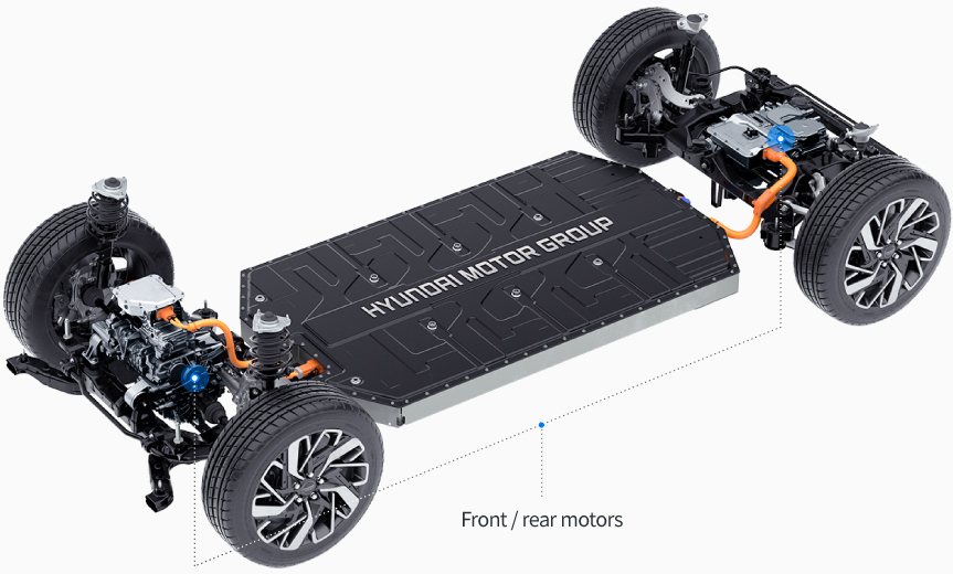
E-GMP motor location

Integrated FE system for the E-GMP

Q. One of the innovative features of the PE system installed in the E-GMP is that the motor, inverter and EV transmission are integrated into a single unit. What are the advantages of the integration of these parts and why is it so difficult to implement this technology?
Kim Min-Sung | In existing EVs based on internal combustion engine vehicle (ICEV) platforms, each part, such as the motor, inverter and EV transmission, played its role from a separate location. However, in the E-GMP, the motor, inverter and EV transmission are designed to be integrated as a single part. It is difficult to design multiple parts into a single part because the design, development and manufacturing technology of each part must all be internalized.
Despite these technical difficulties, the integration of parts brings a variety of advantages. First, the sizes of the parts can be reduced. Accordingly, we were able to optimize the size (height and overall length) to take up less space when applying the PE system inside the platform. Next, system modularization is also possible. Modularization can be achieved by configuring each part of the vehicle as a minimum unit. Thanks to the motor structure, which is smaller in volume than before, the powertrain could be modularized. As a result, we could provide a ‘frunk’ (front + trunk), which is a storage space at the front of the vehicle body, and at the same time, we were able to maximize the utilization of the space above the rear axle and secure enough space for the battery installation.
Shin Dong-Min | Motors and inverters are parts that require a high-voltage connection. In existing EVs based on an ICEV, the motor and inverter are connected through a high-voltage cable that is connected to the outside. However, in the E-GMP’s PE system, in which the motor and inverter are integrated, the structure has been changed to allow internal connection instead of adding an external cable. As a result, we were able to reduce the sizes of the parts in the PE system and lower the cost and weight. We also improved safety by eliminating the external cable, which is relatively susceptible to damage.

Q. Compared to EVs based on ICEV platforms, how small is the E-GMP motor with the integrated PE system?
Kim Min-Sung | Since the drive system of the existing ICEV platforms and the E-GMP are different from each other, it is difficult to simply compare their size. EVs based on ICEV platforms introduced by the Hyundai Motor Group have used a FWD system so far, but the E-GMP uses a RWD system by default, with the option of 4WD by adding a front-wheel motor depending on the trim levels.
More effective use of space is expected due to the reduction in motor size compared to ICEV platforms. The rear-wheel-drive type E-GMP does not have a motor on the front wheel side, so this space can be utilized as a frunk. A frunk can be offered even for the performance 4WD E-GMP option that uses all four wheels. Of course the size of the frunk is relatively small compared to that of the rear-wheel-drive option due to the front-wheel motor, but space can be found thanks to the relatively small size (70 kW) of the motor.
The E-GMP also makes excellent use of space on the rear-wheel side. The rear-wheel motor is mounted inside the subframe and its height is minimized. This secures space for installing the battery and interior space for the rear seats. When you experience the Hyundai IONIQ 5, the first E-GMP-based BEV, you will definitely feel the difference to the expanded interior space.
Transmission disconnector structure of the E-GMP

Drag load prevention when clutch is released

Q. The E-GMP uses rear-wheel-drive (RWD) by default, with the option of 4WD by adding a front-wheel motor depending on the trim levels. Specifically, the drive system can be freely switched between 2WD and 4WD through the ‘EV Transmission Disconnector’ technology. What are the advantages of this technology?
Hong Sung-Hwa | The structure of the EV transmission disconnector uses technology not easily found in existing BEVs. This technology makes it possible to physically connect and disconnect the drive motor and drive axle freely, which are located on the front wheel side. The drive connection to the front wheels can be engaged or disengaged within 0.4 seconds by attaching and detaching the clutch on the drive axle using a motor-type actuator. The EV transmission disconnector is technology that increases the fuel efficiency by preventing the drag load of the front wheel PE system and at the same time enables dynamic driving, which allows customers to make their drive more enjoyable. Also, the driving range can be improved by about 6 to 8%.
New Battery Design Technology and Safety
Senior Research Engineer Choi Yong-Hwan of Battery Engineering Design Team, Part Leader Kim Woo-Sung of Battery Electronics & Control Engineering Design Team
E-GMP’s battery safety features

Q. Is the battery used in E-GMP a completely new development? What is the difference in the configuration, manufacturing process, etc., as compared with batteries on existing EVs based on an ICEV?
Choi Yong-Hwan | A standardized battery cell with high energy density was developed from scratch for the E-GMP. It uses a Li-ion battery in the same way as existing EVs that are based on ICEV platforms, but the decisive difference is that the battery cell and module were standardized into a single unit in consideration of the development direction of the dedicated platform. If the battery design is standardized like this, the battery capacity can be freely configured by adding or removing modules according to the specifications of the vehicle.
Also, a high-nickel (Hi-Ni) material was applied to the positive electrode on the Li-ion battery to achieve high energy density. The higher the nickel ratio in a battery, the more easily lithium ions can move within the battery, resulting in enhanced energy density. Moreover, high-speed charging performance was improved by applying a dual coating method to reduce the resistance of the battery cell on the negative electrode.
Q. Due to the efficient management of battery power, the driving range of the E-GMP is extended compared against existing BEVs. How was that possible?
Kim Woo-Sung | The efficiency of Li-ion batteries used in general in BEVs is similar, at a level of about 96%. Therefore, an important factor in improving the BEV’s driving range is how accurately the specified battery capacity is measured and used. That is, it is particularly important to accurately reach the target amount when charging the battery, and accurately use up the target capacity.
To achieve these two goals, an accurate ‘state estimation technique’ is required for the battery. When developing the E-GMP, we tested it in various situations, charging and driving it under diverse conditions to improve the accuracy of the battery state estimation. As a result, we were able to find usage patterns for the E-GMP battery system in various conditions and secure high battery state estimation accuracy to within 1% of the error rate under room temperature (20–30˚C).
E-GMP Battery system

Q. In the E-GMP, a large battery is placed low down in the center of the vehicle body. What are some of the technologies that help protect batteries to increase safety?
Choi Yong-Hwan | The E-GMP battery pack is rigidly secured to the vehicle body with the mounting structure of battery-penetrative bolts. Also, we enhanced the rigidity of the vehicle body in conjunction with the battery case. At the same time, the battery protection structure is designed such that the grid structure of the battery case can be firmly secured to the vehicle body to protect against lateral shock. Therefore, battery safety is sufficiently guaranteed for collisions that can occur under normal driving situations.
However, an unexpected shock might occur to the floor of the battery in the case of unusual driving or depending on road conditions. In order to protect the battery sufficiently even under these circumstances, a rigid protective floor cover is applied in the vehicle. Furthermore, the possibility of accidents in various collision scenarios has been eliminated by hiding the high-voltage connector, and safety has been constantly verified through countless self-evaluations.
Despite these battery protection features, if the battery case is damaged due to a direct collision, the battery management system (BMS) checks the stability of the battery cell in real time. If a part becomes damaged, it can be repaired by replacing only part of the battery module. Therefore, repair costs are also expected to be significantly reduced.
Kim Woo-Sung | In addition to technology that protects batteries from external shocks, Hyundai Motor Group is also applying technology that improves the safety of the battery itself. To this end, from the battery manufacturing process to the actual conditions of use, we have enhanced the activities and detection functions that ensure safety. One of the representative features is the ability to detect a battery cell that is behaving abnormally while the battery is in use. As a result, it is possible to notify service centers and customers about the problem to facilitate the response to an emergency situation where an abnormal battery cell is detected during battery charging and in standby mode.
Location and structure of temperature heater in the E-GMP

Q. The E-GMP is equipped with an electric heating system to maintain battery performance in winter. What kind of technology is this?
Choi Yong-Hwan | In the Li-ion batteries used in BEVs, cycles of ‘charging’ and ‘discharging’ are repeated as lithium ions move back and forth between the positive and negative electrodes through liquid electrolytes. The reduction in the battery output happens in winter because electrolytes in a liquid state harden at lower temperatures. Hardened electrolytes cause the movement of lithium ions to slow down, which in turn increases the internal resistance of the battery, resulting in a decrease in the charge/discharge performance. For this reason, charging the battery in winter takes longer than charging at room temperature.
To solve the problem, a heater technology that forcibly raises the temperature of the battery has been utilized in the E-GMP. By instantly raising the temperature of the battery, electrolytes can be kept at room temperature, which enables smoother charging of the battery even at low temperatures. When you experience an E-GMP-powered EV in winter, you will discover that any inconvenience caused by delayed battery charging time has been further eliminated.
Multi-charging System, Fast and Easy, a Whole New World of EV Charging
Senior Research Engineer Lee Ki-Jong of Electric Power Conversion Engineering Design Team, Senior Research Engineer Lee Joong-Woo of Electrification System Test Team
E-GMP’s multi-charging system

Q. The E-GMP boasts the world’s first multi-charging system that can accommodate either 800V or 400V fast charging infrastructure. There are some who think that providing an adapter for fast charging is more ‘cost effective’ than developing a multi-charging system. What is Hyundai’s opinion on this?
Lee Ki-Jong | Commonly known external charging adapters use a low charging current, which inevitably slows down the charging speed. For fast charging, which transfers a lot of power to the battery in a short time, the charging current must be high. For this reason, it is known that there is no adapter that can perform 800V (high-voltage) fast charging with a 400V charging system.
And so, other companies support 800V charging under 400V charging infrastructure using a separately mounted on-board charger with a built-in booster, rather than an adapter. In this case, the consumer has to pay an additional cost of about 1.5 million KRW to purchase the controller, and if it is mounted, about 20 kg of weight will be added to the vehicle.
However, with the E-GMP’s multi-charging system, the motor and inverter are already installed in the vehicle and can boost the voltage from 400V to 800V even when a 400V high-speed charger is used. Therefore, I believe that the E-GMP multi-charging system is far more competitive even in terms of cost effectiveness.
Q. In general, EVs have a system that controls charging speed according to the charging status. Does the E-GMP charging system also apply the technology that takes the charging state of the battery into account?
Lee Joong-Woo | The E-GMP has a system that controls the entire charging process while checking vehicle status information, including the battery, in real time during charging. Typical technology is to adjust the charging speed according to the temperature information of the battery.
In batteries, charging speed, charging performance, and endurance reliability are usually mutually affected depending on the size of the charging current. Under room temperature or warmer conditions, the amount of current is increased to maximize battery charging performance and improve charging speed. On the other hand, at room temperature or below, a strategy of optimally reducing the charging current is adopted to maximize the charging performance while securing the endurance reliability of the battery. In this way, the E-GMP controls the optimized charging current for each temperature to ensure battery charging performance and endurance reliability.
Fail-safe evaluation process for E-GMP’s multi-charging system

Q. The E-GMP has a new charging system design, such as a multi-charging system. If there is a compatibility issue between the new system and the existing charging system, what is the solution to this, and how do you resolve errors occurring during operation?
Lee Joong-Woo | We established the ‘fail-safe evaluation process’ and ‘cooperative control technology’ to secure the safety of the multi-charging system function and to increase compatibility between the existing 400V charging facility and the new 800V high-voltage charger. First, ‘fail-safe’ refers to a series of engineering activities that prevent or minimize harm to the passengers or the entire system due to system failure. The evaluation process consists of five steps to verify whether the functionality of the charging system is properly implemented. If an error or failure is identified during this process, activities for the safety of the user and the protection of the vehicle system are carried out through cooperative control.
The first step of the fail-safe evaluation process is system modelling. In this step, the functions and relationships of the subsystems are verified. In accordance with this process, motors, inverters, batteries, charging-related controllers, etc. are categorized into the subsystems of the multi-charging system. Each subsystem is then subdivided into unit systems of sensors, actuators, controllers, etc.
In the second step, representative failure situations are set for some unit systems respectively, and an analysis of their mutual impact is carried out. The reason for not evaluating failures of the entire unit system is because it is expensive and time-consuming. Furthermore, various failure situations of a unit system eventually result in one specific ‘single fault code’ regardless of whether all or part of them are analyzed. Therefore, it is appropriate in terms of efficiency and optimization to select and analyze some failure modes instead of all failure modes.
The third step is to select evaluation items and an evaluation method. 57 evaluation items are selected for up to seven subsystems: motor, inverter, battery, Integrated Charging Control Unit (ICCU), Vehicle Charging Management System (VCMS), Vehicle Control Unit (VCU), and Electric Vehicle Supply Equipment (EVSE). As an evaluation method, a fault injection test that deliberately introduces a failure situation for each target of failure is applied. The number of evaluation systems and items is subject to change depending on the situation, and the selection of the target for failure and failure mode, time of occurrence, and the number of occurrences are considered comprehensively.
The fourth step is to establish an evaluation development environment and proceed with the evaluation. This consists of establishing a fully-fledged environment to evaluate the items prepared in the previous step. Accordingly, after building an evaluation development environment by preparing vehicles to be evaluated, chargers for evaluation, pinboards and cables for injecting hardware faults, software and data measurement devices for introducing failure situations, and related equipment and laptop for analysis, an evaluation is carried out.
The final step of the fail-safe evaluation process is to analyze the results and draw conclusions. In this step, user safety, system protection, multi-charging function implementation, and robustness for each failure situation are verified. Specifically, the safety and completeness of newly applied parts are verified, and the accuracy of the cooperative control for each charging-related controller is also verified.
Cooperative control technology for the E-GMP multi-charging system

If a problem is identified in the sub-elements of the system during the fail-safe evaluation process, then the cooperative control technology controls the charging system through situational strategies. Accordingly, when a problem is identified in the sub-elements of the E-GMP charging system, the charging system is controlled according to each situational strategy by categorizing it as a ‘hazardous situation’ or a ‘non-hazardous situation’. First, in the case of a normal situation that is not a fault, a strategy towards ‘function reinforcement’ is taken so that the original charging function of the system can be performed as expected in various user conditions and environments (whether hot or cold).
In contrast, in a faulted situation, the various failure modes that can occur from each sub-element of the charging system are primarily analyzed. Thereafter, the results of this analysis are summarized from the perspective of design and quality management. Finally, the cooperative control strategy is configured to prevent electric shock or fire that could jeopardize the user’s safety and system in each failure mode.
With V2L (Vehicle to Load), BEV can be used as a Large-Capacity Auxiliary Battery
Senior Research Engineer Lee Hyuk-Jin of Electric Power Conversion Control Engineering Design Team, Senior Research Engineer Lee Youn-Sik of Electric Power Conversion Engineering Design Team

Q. How do you expect V2L technology, which makes it possible to easily power external devices using the electricity stored in the BEV battery, will affect the future popularity of BEVs?
Lee Hyuk-Jin | There are a lot of advantages to the E-GMP-based electric vehicles. One of them is that, unlike existing EVs based on ICEV platforms, spaces such as the engine bay and transmission tunnel can be fully utilized for interior space. In the future, it is expected that vehicles will highlight not only the performance but also the spacious interior that reflects the individual’s lifestyle. As can be seen in the ‘IONIQ Concept Cabin’ unveiled in September last year, BEVs will expand their utilities to encompass personalized digital spaces, mobile offices and comfortable resting spaces. The provision of both the expansion of usable interior space and the V2L function, which allows external devices to use the BEV battery as a source of power, is expected to greatly contribute to the spread of BEVs, along with an expansion in BEV sales.
The E-GMP V2L(Vehicle to Load) function

Q. BEVs from other companies are also equipped with functions similar to V2L. What are the differentiating factors of the V2L installed in the E-GMP?
Lee Youn-Sik | The biggest differentiating factor is that the V2L function can be easily used without a separate AC power supply device inside or outside the vehicle. In the case of BEVs from other companies, a separate power supply device must be purchased to use electronic tproducts that require 3 kW or higher power with the V2L function. However, the price of the power supply device is as high as mid-5 million KRW to 10 million KRW, and the weight is also close to 40 kg, which makes it less usable.
In contrast, electronic products that require high power can be used in the E-GMP-based electric vehicles without a separate device. This is possible because the integrated charging control unit (ICCU) is applied to the E-GMP. The ICCU is a technology newly developed by Hyundai Motor Group to charge both the high-voltage battery and the auxiliary battery in the vehicle. Charging was possible only in one direction in the existing OBC (On Board Charger)*, but this has been improved to enable power conversion in both directions. This allows the electronic products to receive 3.6 kW of high-capacity electric power directly from a vehicle without the need for a separate device.
The 3.6 kW of electric power that can be supplied by the E-GMP is a considerable level, exceeding the 3 kW of domestic contract electric power for housing (electric power to be contracted with Korea Electric Power Corporation and the electric power to be supplied accordingly). In addition, V2L outlets are installed in the E-GMP-based electric vehicles, so passengers can always use high-power electronic products such as induction, TV and refrigerators while driving.
※ OBC: A device that converts power from an external charger to a battery using a charging converter inside the vehicle
Q. With V2L, how many hours can electronic products such as portable induction be used?
Lee Hyuk-Jin | The maximum usage time of V2L can be calculated roughly by taking into account the battery capacity for each vehicle developed based on the E-GMP, the real-time battery charging status and the minimum battery charging level set by the user. Taking this into consideration, when calculating the usage time of electronic products on average, a portable induction with a capacity of 1.5 kW can operate for about 30 hours or longer based on a situation where the BEV’s battery is 100% charged. It is also possible to simultaneously operate an air conditioning unit suitable for a 56 square meter room and a 55-inch TV for about 24 hours. As mentioned earlier, there is no limit to the number of electronic products that can be used at the same time as long as they do not exceed 3.6 kW, which is the maximum power that can be supplied with V2L.