Compared to the Tesla Model S and X, the Model 3 current collector design is quite different.
Why?
We have a reason that we will explain later in the article, but, for now, let’s just review what Tesla did to the current collector design in the Model 3. Then we can speculate on why they were made.
What are current collectors? They do exactly what they are called. They collect current off the individual cells. Many amps worth, and they are not big wires. They are aluminum plates in the Model S and aluminum fingers in the Model 3. Tiny micro fuses attach each cell to the current collectors.
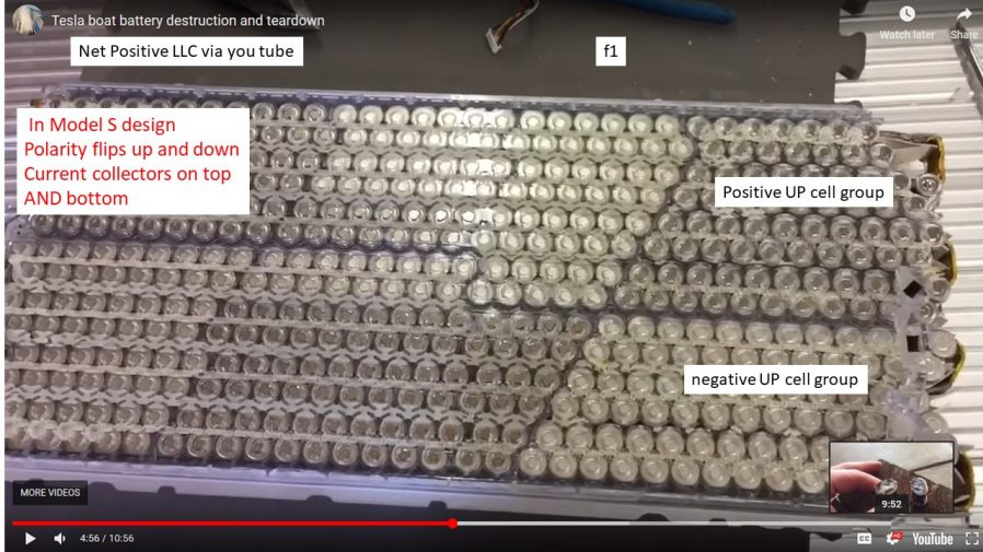
In the Model S there are current collectors on the top AND bottom of each module. Also in the Model S, each parallel cell group flips polarity up and down. Some groups are up and some are down.
Here’s a screen shot from a video by Net Positive LLC on Tesla electric boat battery teardown that shows a module with cell groups switching direction (polarity) up and down. I’ve referred to this video many times as it gives you a great understanding of how the Model S and X battery modules are put together.


In Model S modules the cell group polarity flips up and down. Credit: Net Positive LLC Tesla electric boat battery teardown.
It’s a bit difficult to see in the figure, so we made a simplified schematic that illustrates the current collectors on both sides and the polarity switching up and down in Model S and X battery modules.


In the Model S and X the current collectors are on both the top and the bottom of the module and cell group polarity switches up and down.
What are the big changes in Model 3 modules?
In the Model 3, the cells all point in the same direction. They don’t flip up and down as in the Model S and X. Also, ALL the current collectors are now on the same side of the cells … and get this: the cells all face positive-end down, with current collectors on the BOTTOM of the module.
Inquiring minds might want to know, since both negative AND positive current collectors are on the same (positive) end of the cells, how does the negative end of the cell get connected to the current collector on the other side? Does Tesla run a wire from the negative end of the battery to the collector? No, it’s a totally simple, totally out-of-the-box solution. Remember that the negative side of the cell includes the whole cell case, not just a button on the end. Tesla attaches the micro fuse to the EDGE of the cell case.
You can see that in the following screen shot from Autoline After Hours with Sandy Munro.


Tesla attaches the negative micro fuse to the EDGE of the battery case. Credit Autoline After Hours, Munro and Associates
Here’s another marked up screen shot that shows how the collector gathers all the current from the positive side of the cell group. Then overlapping the next parallel cell group, another set of micro wires feed into the negative ends of the batteries in the next cell group.


Screen shot showing how the current collection gets done all on one side of the module in the Model 3. (Original photo credit Munro and Associates: Markups by Bower and Ritter)
Great example of thinking outside the box.
The screen shot is a bit difficult to see, so we made another simplified sketch showing all the current collectors on one side, with all polarity going the same direction and the current collectors on the bottom.


Schematic showing Model 3 module with all current collectors on the bottom and with all cell’s polarity in the same direction.
Below is a screen shot that verifies that the current collectors are on the BOTTOM of the module in the Model 3. You can see that the little attachment feet on the module, which are on the bottom, are on the same side as the current collectors (the down side).


Screen shot verifying that current collectors are on the BOTTOM of the module in the Model 3. Credit Munro and Associates.
Why did Tesla do this? We can only guess. Our guess is that the new Bandolier design of the Model 3 modules and Grohmann’s automated assembly machine worked better with this set up. Another reason: Lighter current collectors, since they are now fingers instead of big plates, and thinner resulting in a shorter pack since there’s only one plate thickness and not two like in the Model S.
Now here’s another totally off-the-wall reason why Tesla made the changes:
It leaves the design open to be easily adaptable to a flat plate cooling scheme. The smooth negative side of the cells are available to mate up to a flat cooling plate. You ask: Why would Tesla want to switch to a flat plate design that we know from a detailed thermal analysis is inferior to Tesla’s cooling snake?
Ease of assembly and cost. Also, the flat plate design could double as a structural member between the multiple layers of battery in the semi-truck design and would allow tighter spacing between the cells, exactly like the Rivian pack.
Unfortunately, we see the flat plate design only being suitable for the semi-truck battery pack because cooling should not be as big an issue on the semi-truck since it only discharges at a C rate of around one which should minimize heat rejection. Sedans like the Model 3 would still need the cooling snake because of the higher discharge rates and track mode.
Do we really think the semi will use a flat plate design? Probably unlikely since it would destroy commonality between semi and Model 3 modules, but it’s fun speculation nonetheless.
Let us know in the comment section why you think Tesla made the big changes to the Model 3 pack we just described.
This article was a co-production with the author and Keith Ritter