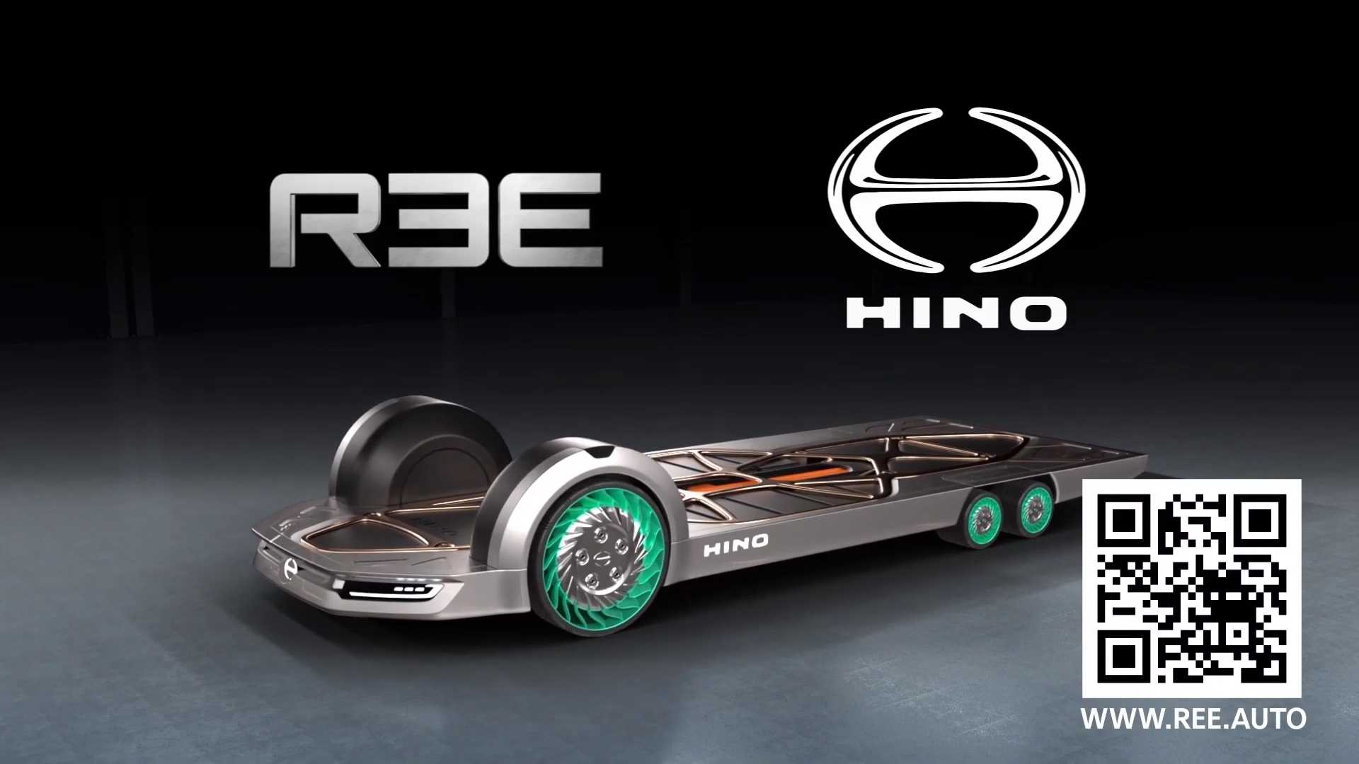
The system arrangement is now clearer than ever.
Our first article on REE raised more doubts than it managed to obtain answers. Then we had the chance to meet Ran Dekel, the automotive team leader for the company. He clarified more aspects of the innovative system, but we were still not very sure about how it worked. The Tokyo Motor Show proved very useful in understanding the concept, now backed up by Hino. If you have never heard of this brand, it is Toyota’s truck division. Both companies have presented the FlatFormer, a chassis for commercial vehicle applications.
Gallery: REE And Hino Present Innovative In-Wheel Motor Technology
The video above shows the FlatFormer is a 6×6 vehicle with tiny rear wheels and larger front wheels. The structure of the in-wheel REE system is presented in detail.
First, you get what looks like a regular wheel rim. The one in the FlatFormer actually looks like one of those airless tires, but we cannot say that for sure, so let’s stick with a regular wheel just as an example of how REE’s system works.

The wheel is directly bolted to the electric motor – as it would be to a regular car’s wheel hub. The electric motor is the interface between the wheels and the REE in-wheel system. It manages not to increase unsprung mass because it just happens to move inside the wheel, even if it is actually attached to the car structure.

After the motor, we have the brake system. The motor seems to be directly linked to the disc.

The brake caliper joins a knuckle to which the motor seems to be horizontally connected. Between these two parts is a data unit, probably the brain of the whole thing. We’ll have to confirm that with Dekel.

This knuckle deals both with the motor and the suspension/steering unit, which crosses the knuckle vertically, and it attached to it in a way we are still not able to explain.

The suspension and the steering are concentrated in a single cylinder. At the bottom of the cylinder is the steering unit, a very compact and strong motor that moves the cylinder, the knuckle, and everything connected to these parts. Inside it is the suspension, which allows the vehicle to have a 150 mm travel in a 17-inch wheel. We have no idea how big the FlatFormer front wheels are, but they look larger than 17-inch units.

The suspension/steering unit cylinder is bolted to the 4-Point RTS (Rapid Turnaround System). Have a better look at it from behind.

Did you see it has four bolts? That’s all that connects the REE in-wheel system to the platform. In case there is any issue with it, just take the screws out and replace the whole REE in-wheel system. That takes less than 15 minutes, according to Dekel.

Summing up, you connect the REE system to the platform with four bolts. They hold the RTS there, which is linked to the suspension/steering cylinder. When the steering unit turns the cylinder, it moves a knuckle to which the motor and the brake are connected. The wheel is connected to the motor. And that’s pretty much how all this works.

The FlatFormer also shows a different arrangement for the rear wheels. It presents an integrated suspension and a drive arm that suppresses the in-wheel suspension cylinder. It is horizontal and placed inside the horizontal RTS, as the picture below shows.

Both wheels have single motor, suspension, and brake. The motor probably powers gears that move both wheels, and the horizontal suspension connects both of them. When one of them moves up or down, a suspension arm turns that vertical movement into a horizontal stroke the single damper absorbs.

The single brake works as chassis brakes, and it is directly connected to the electric motor, which is placed in the most internal part of the platform. This REE in-wheel motor system seems to be attached to the platform precisely like the other one, but we also need to check.

With Hino – and Toyota – showing a concept based on its idea, REE goes from being an Israeli startup to a company that can make the way we produce cars for good. Will we ever see a vehicle based on FlatFormer? We would not bet against that. Not anymore.

